How far can I place a PMP from the tap-in point? (update)
Posted May 9th 2023
In an earlier blog post, we took a look at what happens when we monitor an E1/T1 line with an incorrectly placed monitor point. In this post, we repeat the measurements with a high-quality oscilloscope.
What are we doing?
When monitoring an E1/T1 line in the standard (ITU-T G.772) way, you have a tap-in point and resistors near the tap-in point:
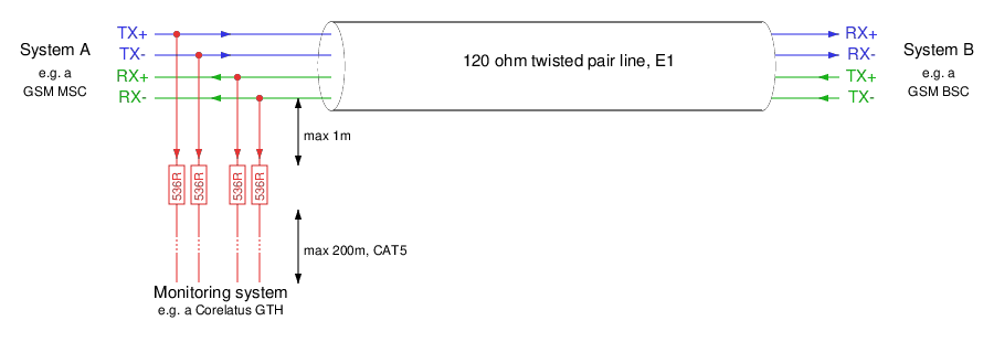
There are two distances marked on the schematic:
From the tap-in point to the resistors: this distance is critical. The shorter, the better.
From the resistors to the monitoring equipment: we have a lot of leeway. Tens of metres is normal, up to 200 metres is possible.
A practical lab monitor point
We created this demonstration in our lab with a live E1 link, and varied the cable lengths to demonstrate various effects on the signal.
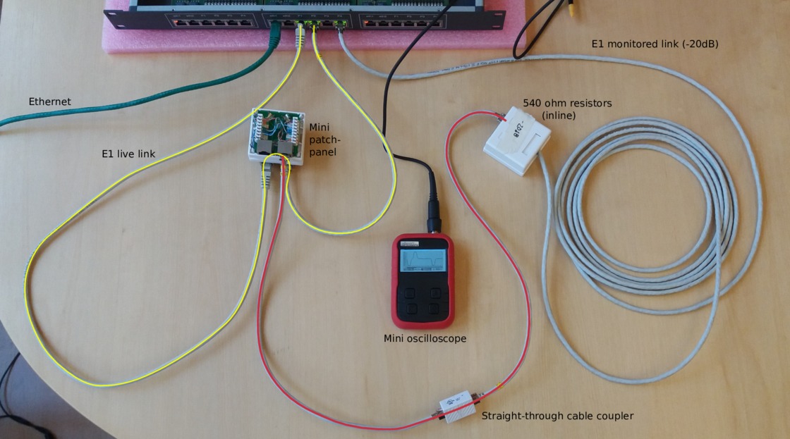
In the photo, we've got a pocket oscilloscope. For this post, we replaced the pocket oscilloscope with a 5 giga-sample/s Teledyne digital storage oscilloscope, to get better measurements. (That's way more than we need for an E1 line.)
Live signal with a 0.5 metre tap-resistor distance
Here's what the live signal looks like in a correctly monitored setup, i.e. the one in the photo above.
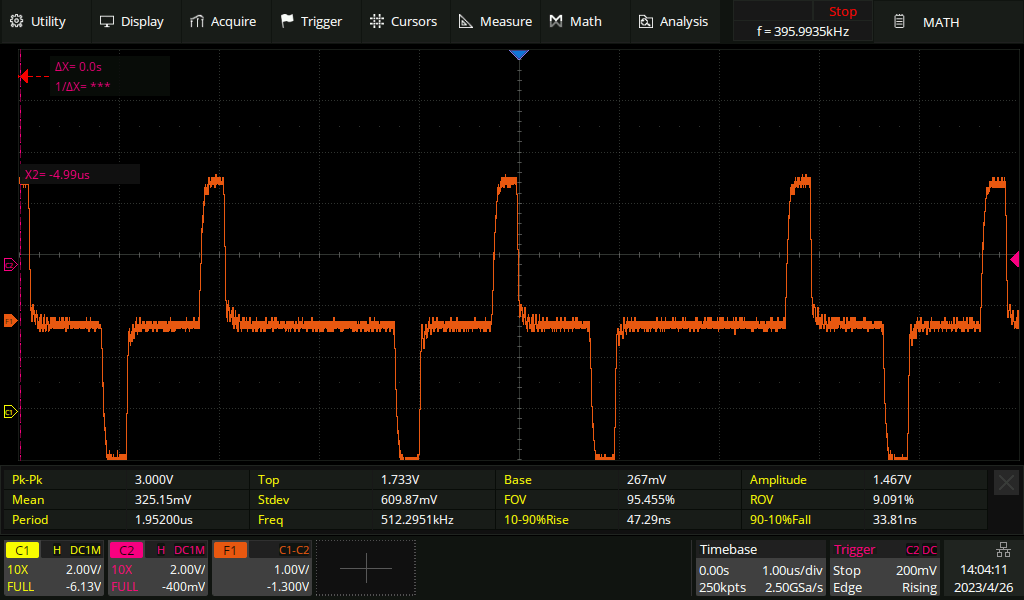
The addition of the monitor point hasn't noticeably affected the live signal.
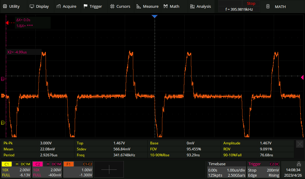
Live signal with a five metre tap-resistor distance
If we extend the tap-in to resistor distance to five metres, then the live signal becomes noticeably affected. The pulse has become slightly deformed, especially on the trailing edge. If the live link was extremely long haul, then we might be unlucky enough to cause it to go from "barely works" to "no longer reliable".
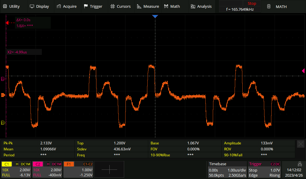
Live signal with a 50 metre tap-resistor distance
If we keep going and extend the distance to 50 metres, the live signal is now affected to the point that it'll no longer work reliably. We can see an extra pulse after every real pulse:
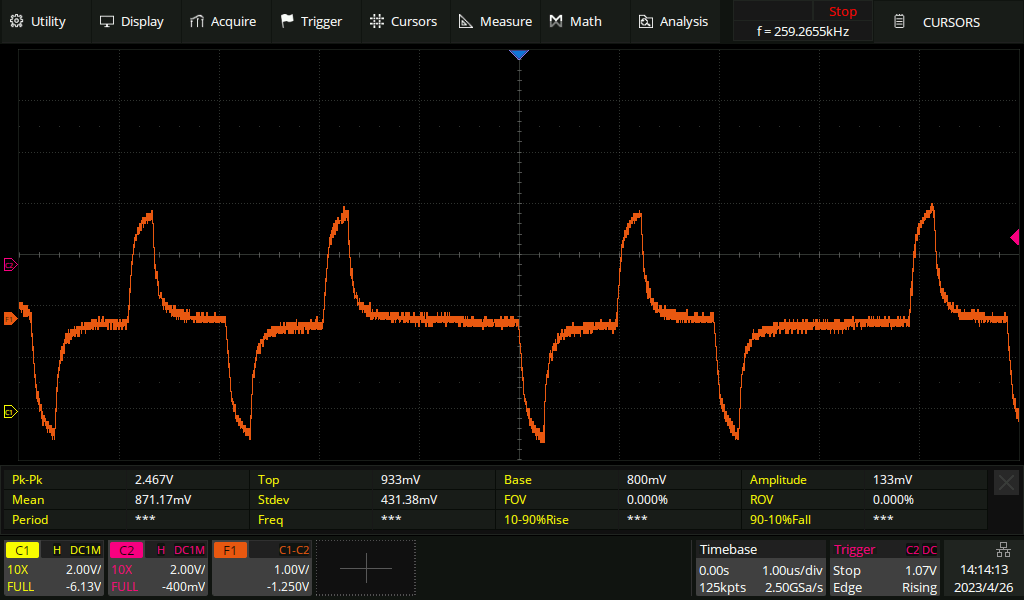
Live signal on a long haul line
All of the above measurements were made with a short live E1 line, only a metre or two. For comparison, here's what an E1 looks like after 200 metres of cable. The pulses become shark-fin like. The receiving equipment expects this and has no trouble decoding the signal.
Permalink | Tags: GTH, telecom-signalling