Revised 26. August 2025
- Operating System
- Ethernet and IP
- Why is the GTH/STH sending UDP packets to port 9 on my network?
- Why is putting both ethernet interfaces on the same subnet not recommended?
- Why can't I reach a GTH/STH on the other side of a gateway?
- Is Ethernet speed auto-negotiation supported?
- What happens if I connect a 100Mbit Ethernet port to a switch which does not support auto-negotiation?
- How can I SSH in to systems running old firmware?
- G.703 E1/T1 Layer 1
- Monitoring E1/T1 Links
- What is passive (unintrusive) monitoring?
- Where along the line must the monitor point be installed?
- What happens if the monitor point is installed far from the tap-in point?
- What happens if a monitoring system is connected without a protected monitor point?
- How can I monitor 75 ohm (coax) E1 lines?
- Where can I buy E1/T1 monitor points, baluns and patch panels?
- What is intrusive monitoring?
- What does a MUX/DXC do?
- What does a groomer do?
- Monitoring SDH/SONET Links
- Which SFPs has Corelatus used on STM-1?
- Can I use SFPs specified as only suitable for Ethernet?
- Which optical splitter should I use?
- How is "link loss" estimated?
- Can you show an example with an optical splitter?
- How do I know how many dB a connector or splitter loses?
- In your experience, which connectors/fibers are most common?
- Do you recommend using a fiber cleaning kit?
- Layer 2 Signalling
- Can you summarise the basic layer 2 (L2) functions in the transmission systems used by Corelatus hardware?
- Why does MTP-2 produce data even when L1 indicates LOS?
- Why does my application occasionally receive MTP-2 packets with length=0?
- What do the internal error messages relating to signalling sockets mean?
- Why can the signalling load meter be higher than 100%?
- Hardware
- How can I identify Corelatus hardware?
- How do I make a straight Ethernet cable?
- How do I make a crossed E1/T1 cable?
- What power supply can I use?
- Can I use power-over-ethernet for redundant power supply?
- What power supply can I use for demos?
- What fuse should I use?
- Do you have artwork for drawing rack images?
- What are the differences between hardware revisions and models?
- Logistics
- Warranty and Support
- End-of-life
1. Operating System
How can I shut down a GTH or STH?
Turn the power off. Corelatus hardware does not require any special preparation before power is turned off.
The API <reset> command can be used to initiate a warm boot.
Why are log timestamps during boot zero?
The realtime clock is set during the boot process, so all items logged before the clock is set show the time since boot instead of "wall time":
          Jan  1 00:00:06 (none) syslog.info klogd: Frame Relay RX driver
          Jan  1 00:00:07 (none) syslog.info klogd: stream_dev
          Aug 12 14:03:10 (none) user.info fpga: Programming fpga
          Aug 12 14:03:11 (none) daemon.info klogd: Power 1 on
          Aug 12 14:03:11 (none) daemon.info klogd: Power 2 off
In the above example, the clock was set immediately before the "Programming fpga" entry.
What do the LEDs show during boot?
All Corelatus hardware uses the same LED pattern during startup. The LEDs in the leftmost RJ45 socket show what is happening:
2 seconds after power-on
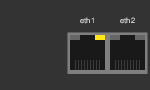
The LEDs are in the 'boot' state, which is the only time this LED can be yellow.
16 seconds after power-on
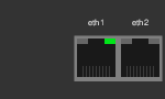
The LEDs change to their normal state. In this example, the green LED means that eth1 has a link.
It takes a module about 30s to go from power-on to accepting API and HTTP connections.
In operation, but with the ethernet unplugged
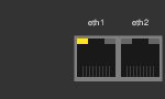
Notice how this differs from the LED pattern on a booting module.
The Getting Started Guides (part numbers 10-0005, 10-0006, 10-0010 and 10-0011) have complete explanations of what various LEDs indicate, as well as pin-out tables.
2. Ethernet and IP
Why is the GTH/STH sending UDP packets to port 9 on my network?
After power-up, GTHs and STHs send one packet per minute on all activated ethernet interfaces until a successful connection is made to the WWW server (at port 8888), the API (port 2089) or SSH (port 22).
This is useful if you have a GTH or STH and don't know what its IP address is. A network sniffer (such as tcpdump or wireshark) will show these 'chirp' packets.
Wireshark is available for most operating systems from https://www.wireshark.org/
Why is putting both ethernet interfaces on the same subnet not recommended?
Whenever the OS sends a packet, it looks at its routing tables to decide which interface to send the packet on. If you have two interfaces on the same subnet, the first interface which matches the subnet will be used to send all the packets, which is probably not what you wanted.
Reference: RFC 1122 section (section 3.3.4.2)
Reference: RFC 2328 (OSPF)
There are various trouble-prone ways to work around this restriction.
Why can't I reach a GTH/STH on the other side of a gateway?
By default, systems are configured without a default gateway (route). You can only reach a GTH/STH which is on the same subnet as the host.
A default gateway can be configured using API commands.
Is Ethernet speed auto-negotiation supported?
Current models (STH 3.0 and GTH 3.0) support Ethernet auto-negotiation on both Ethernet interfaces. Depending on the capabilities of the Ethernet port the GTH is connected to, it runs at either 10 or 100Mbit/s, either half- or full-duplex.
The superseded (in 2006) GTH 1.x only supported auto-negotiation on one of its two ports.
What happens if I connect a 100Mbit Ethernet port to a switch which does not support auto-negotiation?
The GTH or STH will sense the link speed and run at that speed (either 10 or 100Mbit/s. The GTH or STH will assume half-duplex. This behaviour is required by IEEE 802.3:2000.
Some 10/100Mbit/s Ethernet devices, such as high-end switches, allow auto-negotiation to be disabled and the link speed/duplex setting to be manually configured. Several possible configurations will result in problems:
| Remote port configuration | GTH/STH will use | Comment |
|---|---|---|
| auto-negotiate | 100Mbit/s full-duplex | Good (recommended) |
| 100Mbit/s full-duplex | 100Mbit/s half-duplex | Not recommended (see below) |
| 100Mbit/s half-duplex | 100Mbit/s half-duplex | Acceptable |
| 10Mbit/s full-duplex | 10Mbit/s half-duplex | Not recommended (see below) |
| 10Mbit/s half-duplex | 10Mbit/s half-duplex | Acceptable |
The not recommended configurations result in network performance problems, including late collisions. This causes quite confusing symptoms: typically the network works well at low load but then suffers from drastically reduced TCP throughput as the load rises.
References:
IEEE 802.3:2000 (The "Fast Ethernet" specification)
CISCO tech note 17053: "Troubleshooting Cisco Catalyst Switches to NIC Compatibility Issues"
How can I SSH in to systems running old firmware?
In 2015, OpenSSH 7.0 deprecated many weaker (older) ciphers. Old versions of Corelatus firmware only offer old ciphers when logging in via SSH. Therefore, the combination of modern (7.0 and later) SSH and old (before 2016) Corelatus firmware won't allow a login by default.
The proper solution is to upgrade the Corelatus firmware to the most recent version. A hack is to ask OpenSSH to use the deprecated ciphers:
ssh -oKexAlgorithms=+diffie-hellman-group1-sha1 -oHostKeyAlgorithms=+ssh-dss -c +3des-cbc cli@172.16.1.10
3. G.703 E1/T1 Layer 1
What do the E1/T1 Layer 1 (L1) states mean?
- LOS
- Loss of signal. There is no signal strong enough to
detect on the incoming line. In North America, this is
often called a "red alarm". Typical causes:
- no cable plugged in, or cable plugged in to the wrong port
- incorrectly wired cable
- incorrect monitor point construction (i.e. the monitor point's attenuation lies outside the nominal 17-23 dB range)
- The GTH system not configured for monitoring even though the input signal is -20 dB from nominal.
- LFA
- Loss of frame alignment. There is a signal on the
line, but E1 (or T1) framing cannot be recovered.
In North America, this is often also called a "red alarm".
Typical causes:
- Incorrect L1 configuration, e.g. the incoming line may be T1 but the GTH is configured for E1, or the incoming line may be doubleframe but the L1 is configured for multiframe.
- Attempting to monitor a signal which is neither E1 nor T1. For instance, attempting to monitor an HDSL modem on its analog line port instead of its E1 port will result in LFA.
- LMFA
- Loss of multiframe alignment. There is a signal on the line and framing can be recovered, but multiframe framing cannot be recovered. Typical cause: incorrect L1 configuration.
- AIS
- Alarm indication signal. The E1 receiver in the GTH has detected a fault on the signal it is receiving (too many 1-bits in a frame). This is often called a "blue alarm" in North America. Typical cause: incorrect L1 configuration.
- RAI
- Remote alarm indication. The E1 receiver in the
equipment being monitored (i.e. not the GTH) has detected
an LOS, LFA or LMFA condition in the signal it is receiving.
This is often called a "yellow alarm" in North America.
Typical causes when using a monitor point:
- Incorrectly wired or incorrectly installed monitor point which interrupts the signal on the line being monitored.
- Fault in the line being monitored.
- Fault in the transmitter on the other pair of the line being monitored.
- Fault in the receiver on the other pair of the line being monitored.
- Incorrectly wired cable.
- GTH L1 parameters incorrectly configured, e.g. monitoring enabled, or configured for T1 when attached to an E1 system.
What do the E1/T1 L1 Error counters represent?
The GTH maintains a number of error counters for each receiver. The counters can be used to help diagnose a number of L1 problems.
- Slip
- The number of positive and negative slips. Slips are
covered in more detail in later questions. Typical causes:
- The operator's PDH network is not maintaining correct internal sync. Understanding the operator's sync topology is a pre-requisite to troubleshooting this problem.
- GTH is (mis-)configured to use its internal frequency reference when it should be configured as a sync slave to one of the E1/T1 inputs.
- GTH is unable to find a sync source, for instance because the framing configuration is incorrect. One example is configuring GTH for multiframe when the link is actually doubleframe.
- Frame Error
- The incoming signal did not conform to the
expected framing. Typical causes:
- Incorrect framing configuration, e.g. GTH configured for multiframe, whereas the link is actually doubleframe.
- Incoming signal is not an E1 signal, e.g. attempting to monitor a DSL line can give this symptom.
- Incoming signal contains too much noise to decode correctly.
- Code violation
- The incoming signal did not conform to the
expected signal coding rules. Typical causes:
- Incorrect coding configuration, e.g. GTH configured for HDB3 coding (used on all E1 links) but the incoming signal is actually T1 (which uses B8ZS coding). In most cases, this will cause hundreds or thousands of code violations per second.
- Incoming signal is not an E1 signal, e.g. attempting to monitor a DSL line can cause this symptom.
- Excessively weak incoming signal. Use a handheld signal tester or an oscilloscope to verify that the signal strength is as expected.
- Incorrect monitoring configuration, e.g. GTH is configured for -20 dB monitoring, but the incoming signal is not attenuated.
- Line noise/interruption. A small number of code violations is normal. In some installations, this can be as low as five or ten code violations per link per month. Error rates greater than a few tens of violations per day are usually worth investigating.
- CRC error
- The Layer 1 data integrity check (a CRC check)
failed. The counter shows how many times the check
failed.
This counter is only used when the GTH is
configured for multiframe framing.
Typical causes:
- Line noise. A small number of CRC errors is normal. In some installations, this can be as low as five or ten per link per month.
- Incorrect framing configuration, e.g. GTH configured for multiframe, link is actually doubleframe.
Can you explain, briefly, how sync works in PDH networks?
E1 (and T1) lines are part of the 'PDH' network. PDH stands for plesiosynchronous digital hierarchy, meaning that the whole network runs with "almost" synchronised clocks.
Every switch in a PDH network must have a source for its 8kHz sync. Possible sync sources are:
- An internal oscillator
- An E1 cable
- A special sync input
PDH requires all switches in a network to run "almost" synchronised. In practice, this is done by specifying master/slave sync relationships between the switches:
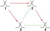
| A simple, correct, sync network |
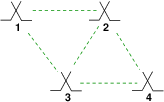
The dashed green lines indicate E1 cables between switches. The solid lines with arrows indicate a master/slave sync relationship: switch 4 uses switch 2 as its sync master. Switch 1 has no master, it is the sync reference for the whole network.
There are many ways to mis-configure networks such that sync will not work. The diagrams show a few common ones.
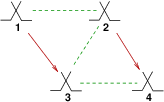
| Misconfigured: two sync masters. Neither switch 1 nor switch 2 has a master. Both generate their frequency reference internally. Expect slips on E1s 1-2, 2-3 and 3-4. |
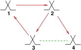
| Misconfigured: all switches unsynchronised. Expect slips on all E1s. |
| Misconfigured: a circular sync relationship. Each switch 'chases' the next switch. Expect unpredictable behaviour. |
The last example, the circular sync relationship, is the worst. A common result of such a configuration is that the frequency migrates to the extreme of the sync range the equipment can handle, thus taking it outside the frequency limits allowed by G.703.
The ITU-T standard G.781 contains further information about synchronisation hierarchies in PDH networks.
What happens when there is a slip?
A slip occurs when a transmitter emits frames at a different rate to the rate the receiver accepts the frames. When the transmitter's rate is greater than the receiver's, the receiver deals with the situation by discarding one frame every so often.
Conversely, when the transmitter's rate is lower than the receiver's the receiver duplicates a frame every so often.
On E1, a frame is 32 octets of data, one octet per timeslot.
On voice circuits, a slip results in an audible 'pop'. On signalling circuits it results in corrupted packets. In MTP-2, a slip will (almost) always result in one corrupted packet.
How does sync work on the GTH?
This is described in detail in section 7.2 of the API manual ("Sync sources"). By default, the GTH will automatically select an E1/T1 input to synchronise to. The GTH will adjust its internal frequency to match the chosen interface, as long as the E1/T1 line's frequency is within the limits specified by G.703. (+/- 50ppm)
The GTH's sync behaviour can also be manually configured, either to use a particular line as its sync source, or to use its internal oscillator. Example: to set the sync source to PCM2A:
          <set name="sync">
          <attribute name="source" value="pcm2A"/>
          </set>
The stability of the GTH's internal oscillator is +/- 1 ppm, within the normal temperature range. This stability determines the performance in situations where the sync source is temporarily lost, in practice it means the GTH can tolerate sync loss for approximately two minutes without having to slip.
How is "ppm" related to packet loss rate?
ppm means parts-per-million. Thus if one system runs at 8000Hz and another at 8000.2Hz, they differ by 250ppm. The time between slips is given by 1/(d x R), where 'd' is the frequency error and R is the frame rate.
Examples:
| d | R | Time between slips |
|---|---|---|
| 1ppm | 8000 frames/s | 125 seconds |
| 50ppm | 8000 | 2.5 seconds |
In MTP-2, packets are transmitted continuously, so a slip will (almost) always damage a packet. On an "idle" MTP-2 link, the wire has nonstop 5 octet FISUs, a 50ppm frequency error should give about 24 damaged FISUs per minute. These are counted as ESUs.
Why is Ethernet "immune" from slips?
10Mbit/s and 100Mbit/s ethernet links re-synchronise at the start of each transmitted packet.
In most applications, this means there are never slips. In applications which transmit fixed-rate data, e.g. a VOIP system, slips still occur. They are usually dealt with in an application-specific way. VOIP systems often use "silence compression/expansion" to hide the slips.
4. Monitoring E1/T1 Links
What is passive (unintrusive) monitoring?
Passive monitoring means connecting a test instrument, such as a GTH, to an E1 or T1 link without disturbing, or being able to disturb, the link. The GTH can listen in on ("sniff") the signalling and voice traffic on the link, but not change it. Sniffing E1/T1 links is useful in any application that needs to observe without disturbing.
There is a standardised way to monitor E1/T1 links. It is defined in ITU-T G.772 and is formally called a "Protected Monitoring Point". A G.772 protected monitoring point connects to a live line in such a way that the test equipment sees a signal attenuated by 20 dB (one tenth of the signal voltage). One way to do that is with two resistors:
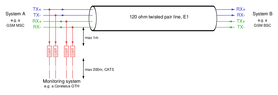
A 120 ohm E1 link with two monitor points (red) inserted.
The diagram shows a 120 ohm installation with 536 ohm resistors. To get 20 dB attenuation, you want 540 ohm. 536 is the closest commonly available resistor, and the diffference does not matter in practice.
In North America, 100 ohm T1 lines are common. Monitoring points for T1 lines typically use 460 or 470 ohm resistors.
One GTH 3.0 module has enough E1/T1 receivers to passively monitor both directions of 32 E1/T1 links.
Where along the line must the monitor point be installed?
A monitor point can be installed at any point between the two systems communicating over an E1/T1 line. Some installations have a patch panel or digital distribution frame (DDF) near one of the two systems, this is a good spot. Some sites have built-in monitor points.
There are some restrictions on the monitor point itself. The distance between the E1/T1 line and the resistors must be short, 1m maximum. The distance from the resistors to the GTH system can be 200m maximum.
What happens if the monitor point is installed far from the tap-in point?
The monitor point diagram above allows a maximum distance of one metre from the tap-in point to the resistor.
If the resistor is placed much further from the tap-in point, then the monitor point will send echoes of the signal back to the live link. The echos will interfere with the live signal and cause bit errors on the live link. The severity of the problem depends on the relative line lengths and can be predicted using tools such as spice.
What happens if a monitoring system is connected without a protected monitor point?
If the monitoring equipment terminates with high impedance, then this configuration will work reliably if the cable from the tap-in point to the monitoring equipment is short, e.g. about 1 metre. Longer cables cause a situation equivalent to the one covered in the previous question, i.e. bit errors on the live link.
If the monitoring equipment terminates with 120 ohm, then the live link will be loaded incorrectly resulting in a lower signal strength and a risk of bit errors or possibly a loss of signal.
How can I monitor 75 ohm (coax) E1 lines?
We recommend this approach:
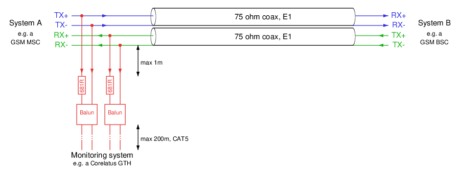
Where can I buy E1/T1 monitor points, baluns and patch panels?
Corelatus supplies -20 dB monitor points suitable for use with E1 or T1 lines.
There are also a number of other manufacturers of equipment for connecting E1 and T1 lines. Some of the ones we've heard of are:
Tekmos (UK) have a wide range of panels, adaptors, baluns and monitor points.
AC&E (Australia) also sell panels, cables and baluns.
Comcraft (USA) sell monitor points for E1 and T1.
Patton (USA) sell monitor points and baluns for E1 and T1.
What is intrusive monitoring?
Intrusive monitoring means unplugging an E1/T1 link and inserting a GTH into the link as an active component. The GTH thus becomes an active part of the network instead of being a passive listener.
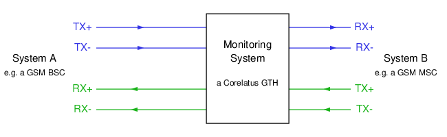
Intrusive monitoring an E1 or T1 link with a GTH
As an active participant in the network, the GTH can enable and disable voice traffic for every timeslot it is connected to. In some applications, such as fraud prevention, this is desirable.
One GTH 2.x module has enough E1/T1 transceivers to intrusively monitor both directions of 8 E1/T1 links.
One GTH 3.0 module has enough E1/T1 transceivers to intrusively monitor both directions of 32 E1/T1 links.
What does a MUX/DXC do?
A MUX or DXC (digital cross-connect) is a piece of equipment which lets you connect many E1/T1 lines and semi-permanently switch them to each other. Typically, they allow timeslot-by-timeslot switching and also copying (aggregating) selected timeslots to a separate E1/T1 line.
One common way to use a DXC is to aggregate the signalling timeslot (often timeslot 16) from many E1/T1 lines onto just a few E1 lines, i.e. by configuring the DXC to copy timeslot 16 from one E1/T1 to timeslot 1, timeslot 16 from another E1/T1 to timeslot 2 and so on. This reduces the amount of cabling leading to a GTH.
When a GTH's input comes from a MUX or DXC, the GTH's L1 information shows the status of the E1/T1 line coming from the MUX, i.e. it shows whether the MUX is transmitting a good signal or not. The status of the E1/T1 lines in the network is only known to the MUX. Most MUX/DXCs have an O&M interface which can show the hidden L1 information, higher end models also show some L1 counters.
What does a groomer do?
A groomer is a variant of a MUX/DXC designed specifically for aggregating signalling. Some groomers are able to recover -20 dB signals from monitor points.
5. Monitoring SDH/SONET Links
Which SFPs has Corelatus used on STM-1?
We have used SFPs from Coherent (previously II-VI and Finisar), Formerica, Planet, Luminent and MRV. We select SFPs which are specified for:
- 155MHz (OC-3) line rate.
- 3.3 V.
- Support for digital diagnostics monitoring (DDM). One use of DDM is to measure the incoming signal strength.
- The same connectors, fiber type and wavelength the rest of the site uses. In Corelatus' lab, we use LC connectors, single mode fiber and 1310nm wavelength.
- Rx sensitivity -28 dBm or better (more negative numbers indicate greater sensitivity, so -34 dBm is more sensitive than -28 dBm).
Rx sensitivity is usually independent of Tx power, i.e. buying an SFP rated for 30 km of fiber instead of 10 km usually gets you a more powerful transmitter but leaves the receiver sensitivity unchanged.
Coherent has a nice website with full datasheets available online and "Buy Now" links to several distributors.
Can I use SFPs specified as only suitable for Ethernet?
Many SFPs are specified as being suitable for OC-3 and 100BASE-FX Ethernet. These are, of course, fine for use with OC-3 (as used with STM-1).
Some low-cost SFPs are specified as being suitable for Optical Gigabit Ethernet without mentioning OC-3. These will most likely work fine for OC-3, as long as the connector, wavelength, fiber type and sensitivity are suitable. The only way to be sure is to try.
Which optical splitter should I use?
In our lab, we use 50/50, 80/20 and 90/10 taps. A 90/10 tap disturbs the live link the least, so we recommend using them whenever the link loss to the STH allows it.
Three suppliers of taps:
How is "link loss" estimated?
One end of an optical link transmits light. The other end receives light. On the way from one end to the other, some of the light is lost. A link loss budget is a list of how much light you expect to lose along the way. The point of the budget is to make sure you haven't lost too much.
Here's an example. We'll assume we're using Formerica TSD-SXAA1-H11 SFPs at both ends, that the link is 10km long and uses 9µm fiber and that each connector loses about 1 dB:

The signal starts off at -9 dBm at the transmitter (the data sheet for the SFP specifies the optical output power as between -9 and -3 dBm). The connector on the SFP loses 1dB. The 10 km long fiber loses roughly 0.5 dB per kilometer and the connector on the far-side SFP loses another 1 dB. That leaves -9 - 1 - 5 - 1 = -16 dBm of signal available at the SFP input. The SFP is rated to recover signals from -3 to -34 dBm. -16 dBm falls comfortably inside that range.
Can you show an example with an optical splitter?
Using the same link as in the previous question, but inserting a 90/10 splitter:
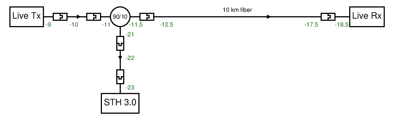
In this example, the power available for the live link's receiver is affected slightly by the splitter and its connectors: instead of -16 dBm, it's now -18.5 dBm. This still leaves a comfortable margin.
The STH sees a -23 dBm input signal.
How do I know how many dB a connector or splitter loses?
The examples above use conservative values. That's ok for a quick estimate. For more accurate work, consult the datasheet for the connectors, patch panels, splitters and fibers you have.
In the example with the optical splitter, the total insertion losses are 2.5 dB on the live link and -12 dB on the leg to the STH. The datasheet for the 90/10 taps Corelatus uses in the lab actually specifies just 0.8 dB and 12 dB as the maximum losses—i.e. they're a bit better than the example assumed.
You can also calculate the lowest possible loss in a splitter by directly applying the definition of dB. For a 90/10 splitter:
Loss on the '90' leg: 10 · log 0.9 = -0.46 dB
Loss on the '10' leg: 10 · log 0.1 = -10.0 dB
In your experience, which connectors/fibers are most common?
Connectors: Most sites use LC connectors. We have seen a small number with SC.
Fiber type: For long-haul (e.g. 30 km), all the installations we have seen are 'single mode fiber' (SMF). For short-haul, i.e. patching within a site, we've seen some operators used SMF, perhaps because they want to keep things simple, whereas others use multi mode fiber (MMF), perhaps to keep costs down.
Do you recommend using a fiber cleaning kit?
Yes. Dirty connectors or SFPs cause unexpectedly low optical RX readings. Cleaning all connectors when installing a system is much quicker than troubleshooting a system to find the dirty connector.
Kits are are from about 50 EUR up to 300 EUR from places which sell SFPs and fiber patch cables.
6. Layer 2 Signalling
Can you summarise the basic layer 2 (L2) functions in the transmission systems used by Corelatus hardware?
| Ethernet/IP | E1/HDLC | ATM | |
|---|---|---|---|
| What happens when there is no data to send? | Electrical silence (no voltage on the line) | MTP-2: send FISU LAPD/FR: send FLAG |
Send "idle" cell or "unassigned" cell |
| How does the hardware find the start of a packet? | Watch for the transition from electrical silence to a "preamble" sequence which must come before every packet. The preamble sequence is 80 bits of 101010... It has the secondary function of synchronising clocks. | Find a flag (bit pattern 01111110) followed by a non-flag. Bit stuffing guarantees that FLAG never occurs inside a packet. | Next packet (cell) always comes exactly 53 octets after start of current. At startup, we find the start of a packet by just starting somewhere and computing the header CRC. If it's wrong, we move forward one octet and try again. When we find a correct CRC, we move forward 53 octets and see if that header is also correct. |
| What are the alignment requirements? | (Not relevant) | No alignment requirements at all, not even octet alignment. | Cells are octet aligned, but not frame aligned. A cell must always start on an octet boundary. A cell will usually not start on a frame boundary. |
| How are bit errors detected? | 32-bit CRC after every frame (packet) | 16-bit CRC after every signal unit (packet) | Cell header (5 octets) protected by an 8-bit CRC.
AAL0: No payload protection. AAL2: No payload protection (but 5 bit CRC on secondary header). SSCS sublayer may add a 10-bit CRC. AAL5: 32-bit CRC on payload |
| How is packet length limited? | Ethernet frame is about 1.5k max.
TCP can reassemble frames with no length limit. UDP limits to 64k | MTP-2: 279 octets.
LAPD: 265 octets by default Frame relay: generally 1.6k | AAL0: Cells are always 53 octets.
AAL2: 45 octets by default (64 octets optional) AAL5: 64k |
Why does MTP-2 produce data even when L1 indicates LOS?
The LOS indication is a warning; it means "the signal is now so weak that correct data extraction cannot be guaranteed". LOS does not itself disable the incoming data stream; the decision whether or not to terminate L2 if L1 indicates LOS is left to the application.
Why does my application occasionally receive MTP-2 packets with length=0?
With ESU filtering disabled (ESU="yes"), the GTH/STH delivers all signal units (packets), including signal units which are less than the minimum length. Some examples of input bitstreams which cause signal units with a zero-byte length:
Four-bit signal unit (zero bytes!): 0111 1110 1011 0111 1110
One-bit signal unit (zero bytes!): 0111 1110 1011 1111 0
Instantly aborted signal unit (also zero bytes): 0111 1110 1111 1111
The same applies to LAPD and Frame Relay.
What do the internal error messages relating to signalling sockets mean?
When sending signalling data, for instance in an MTP-2 monitoring application, some information about sockets going down is logged. This is intended for internal use, but they might be of some use when solving problems. The possible messages are:
killed sock N fd M (poll() event: error/input), errno P
There are two possible reasons for this message.
- The socket was closed remotely, either by the application or the OS.
- Input was received for transmission to a timeslot configured for monitoring.
killed sock N fd M (write failed), errno P
This happens if an attempt to write a socket failed with an error. Some values of P indicate specific problems:
| Code | Cause |
|---|---|
| 32 | The reading end of the socket has closed |
| 104 | The remote OS reset the socket (typical behaviour when a remote program is terminated or a server is rebooted) |
| 110 | The remote connection timed out. This is typical of an ethernet network failure, e.g. a cable has been unplugged. |
Most other values do not indicate an error, in particular 0, 4 and 11 are normal.
In all cases, preceding or following error messages may give provide extra information.
Why can the signalling load meter be higher than 100%?
The current load on a signalling channel is computed over a period of 1s:
current_load(t) = 100 · (Mt - Mt - 1s) / B
Mt is the number of octets contained in correct signalling packets at time t. B is the nominal channel bandwidth in octets-per-second. So the load meter shows the sum of the size of packets arriving in a particular second compared to the underlying link data rate.
Consider a 64kbit/s frame relay link carrying a sequence of packets, each of which 1200 octets long:
| Time (ms) | M | Event |
|---|---|---|
| 0 | 0 | Packet 1 starts |
| 150 | 1200 | Packet 1 ends. Packet 2 starts. |
| 300 | 2400 | Packet 2 ends. Packet 3 starts. |
| 450 | 3600 | Packet 3 ends. Packet 4 starts. |
| 600 | 4800 | Packet 4 ends. Packet 5 starts. |
| 750 | 6000 | Packet 5 ends. Packet 6 starts. |
| 900 | 7200 | Packet 6 ends. Packet 7 starts. |
| 1050 | 8400 | Packet 7 ends. Packet 8 starts. |
| 1200 | 9600 | Packet 8 ends. |
The load measured at instance 1040ms is 100 · (7200 - 0) / 8000 = 90%
The same calculation at instance 1060ms is 100 · (8400 - 0) / 8000 = 105%
The measurement granularity is most significant for slow links (e.g. 64kbit/s) carrying large packets (e.g. frame relay).
The GTH/STH also provides an average load meter which measures the load over a longer period, 30s by default, the API manual describes how to read it.
7. Hardware
How can I identify Corelatus hardware?
There are several identification codes in Corelatus products.
| Name | Location | Purpose |
|---|---|---|
| Chassis serial number (CSN) | On a metallic silver self-adhesive on the left side of the grey steel chassis, immediately following the text "Serial:". | Uniquely identifies each chassis. At delivery time, Corelatus supplies a list of cards in each chassis. |
| Ethernet MAC address | Factory-programmed. Can be viewed via the in-built webserver (on the "ethernet" page) | Uniquely identifies each ethernet interface. |
| ROM ID | Factory-programmed. Can be viewed via the API or SSH CLI. | Uniquely identifies each piece of hardware. |
Corelatus maintains a database which cross-references all of the above information.
How do I make a straight Ethernet cable?
A straight cable is most often used to connect an Ethernet interface to an Ethernet hub or switch. Shielded CAT-5 cable (STP) must be used, the connectors are RJ45.
| End A | Cable | End B |
|---|---|---|
| Pin | Wire Colour | Pin |
| 1 | orange-white | 1 |
| 2 | orange | 2 |
| 3 | green-white | 3 |
| 4 | blue | 4 |
| 5 | blue-white | 5 |
| 6 | green | 6 |
| 7 | brown-white | 7 |
| 8 | brown | 8 |
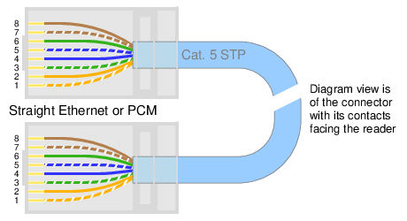
The wire colours have been chosen to follow one of the schemes allowed in EIA/TIA 568 A/B.
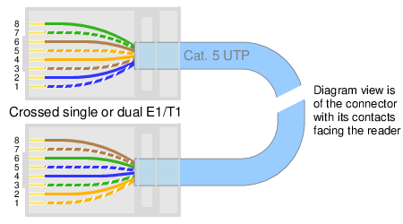
How do I make a crossed E1/T1 cable?
A crossed E1/T1 cable can be used to loop back an E1/T1 port, i.e. make a GTH transmit to itself. The connector is RJ45.
E1 lines are specified for 120 ohm cables. Using CAT-5 or CAT-5e cable (100 ohm) is a bit out-of-spec, which is fine for lab work, but not real installations.
| End A | Cable | End B | ||
|---|---|---|---|---|
| Pin | Name | Wire Colour | Pin | Name |
| 1 | RX A | orange-white | 5 | TX A |
| 2 | RX A | orange | 4 | TX A |
| 3 | RX B | green-white | 7 | TX B |
| 4 | TX A | blue | 2 | RX A |
| 5 | TX A | blue-white | 1 | RX A |
| 6 | RX B | green | 8 | TX B |
| 7 | TX B | brown-white | 3 | RX B |
| 8 | TX B | brown | 6 | RX B |
What power supply can I use?
All Corelatus products run on standard telephone exchange power, i.e. 48V DC.
By far the best way to supply power to a live system is to use a site's existing 48V DC power supply. Most telecom sites have large, battery-backed 48V DC supplies. Connect to them using the cables Corelatus supplies with every system (there are two included in every box).
If there isn't an existing 48V DC power supply, for instance at a small site or in a lab, use a 19" rack-mounted power supply. There are a number of suppliers. In Corelatus' lab, we have a Kepco supply.
These are supplies designed for carriers, e.g. they let you build redundant, hot-swappable systems and are designed to meet NEBS.
Can I use power-over-ethernet for redundant power supply?
Corelatus' GTH 3.0 and STH 3.0 hardware, used in the E1/T1 Monitor 3.0 and SDH Monitor 3.0 products, can use power-over-ethernet (PoE) on both eth1 and eth2.
By using two PoE switches, it is possible to make a dual-power system without needing any conventional 48V DC supplies. There are two practical problems to keep in mind:
- If power from one PoE switch fails, the other switch must increase its power output quickly enough to avoid a temporary loss of power, which in turn causes a reboot. We have seen several models of switches which react too slowly.
- You must take care to avoid inadvertently connecting two power supplies in series, for instance by earthing the wrong side of one supply's output.
Recommendation: if the system is important enough to require dual power supply, prefer conventional 48 V DC supplies. This is simpler and more robust.
What power supply can I use for demos?
Any portable, regulated 48V DC power supply which can supply 25W can be used.
Corelatus uses Mascot 2420/3220/3820 supplies for demonstrations.
Attaching the XLR plug supplied with Corelatus systems to the flying lead on a Mascot supply requires some basic tools: a soldering iron, a small flat-blade screwdriver and a wire stripper.
What fuse should I use?
For a single 19" chassis, use a 2A fuse. If you have multiple chassis and cannot have one fuse for each, you can put several on the same fuse, but the rating must be scaled up.
A "fast" fuse is recommended. Type "MDL/medium" and type "T/slow" are also acceptable.
Do you have artwork for drawing rack images?
Sure. (They're useful if you want to sketch an entire rack layout to help installers put servers, switches and probes in the right places.)
E1/T1 Monitor 3.0:
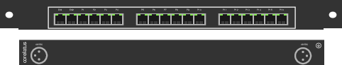
SDH Monitor 3.0:
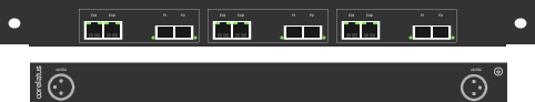
The original, scalable, .eps files:
corelatus_e1t1_monitor_3.0_rack_outline.eps
corelatus_sdh_monitor_3.0_rack_outline.eps
What are the differences between hardware revisions and models?
The major versions of hardware for connecting to electrical E1/T1 interfaces are:
| Model | GTH 3.0 | GTH 2.1 | GTH 1.1 |
|---|---|---|---|
| Shipping years | 2011 onwards | 2006--2019 | 2001--2006 |
| Ethernet ports | 2x10/100 | 2x10/100 | 1x10/100, 1x10 |
| E1/T1 ports (duplex) | - | 8 | 4 |
| E1/T1 ports (monitoring) | 64 | 16 | 4 |
| MTP-2 monitoring | 240 timeslots | 64 | 32 |
| MTP-2 Annex A monitoring | 8 channels | 4 channels | 2 channels |
| (248 timeslots) | (124 timeslots) | ||
| LAPD monitoring | 400 timeslots | 64 timeslots | 32 |
| Frame relay monitoring | 96 channels | 64 channels | 32 channels |
| up to 1488 timeslots | up to 496 timeslots | 4Mbit/s | |
| up to 48 Mbit/s | up to 16 Mbit/s | ||
| ATM monitoring | 16 channels | 6 channels | 2 channels |
| 32 Mbit/s | 12 Mbit/s | 4 Mbit/s |
GTH 3.0, 2.1, 2.0, 1.1 and 1.0 modules use the same software API.
In addition to the above modules, Corelatus also shipped an expansion module, the IEB 1.0, from 2003--2006. The IEB module provided 12 E1/T1 ports, but relied on an adjacent host GTH 1.1 module for processing power and ethernet.
In 2012, Corelatus also started shipping SDH hardware, the STH 3.0. It has capabilities similar to GTH 3.0.
8. Logistics
What packaging do you recommend for international shipping?
A Corelatus plywood shipping crate, which is available on request in conjunction with orders.
What are the packaging dimensions?
E1/T1 Monitor 3.0 and SDH Monitor 3.0 shipped in individual cardboard boxes:
          610mm x 220mm x 80mm
          4 kg
A ready-to-ship Corelatus plywood crate packed with six GTH 3.0 or STH 3.0 systems:
          630mm x 450mm x 240mm (WxDxH)
          0.07 cubic metres (2.4 cubic feet)
          22kg (45 pounds)
Which customs classification number do you use?
We use the customs classification number 85176200 (Telephonic or telegraphic switching apparatus) and country of origin code 30 (Sweden).
Some older documents, e.g. trade agreements, refer to the code 85173000 for the same equipment. Some classification tables shorten the codes, i.e. they use 851762 interchangeably with 85176200.
Which ECCN code applies to Corelatus hardware?
5A991. We most recently checked the classification in January 2021.
9. Warranty and Support
How long is the hardware warranty?
Eighteen months from delivery. During the warranty period, Corelatus will repair or replace, at Corelatus' option, units which are defective due to faulty construction, materials or manufacture.
Two optional extended warranties are available:
- Year-by-year warranty extension can be purchased for 10% per year. This type of extension can be purchased at any time before the current warranty expires.
- Alternatively, a one-off extension to a total of five years can be purchased for 20%. This extension can only be purchased before delivery.
What is the turnaround time for repairs and replacements?
Maximum six weeks.
For how long do you provide support?
All systems are supported for at least three years from sale.
Additionally, systems with extended warranties are supported until the warranty expires.
Support includes free firmware updates, email and telephone support during (Stockholm) business hours to developers (but not to operators/end-users).
10. End-of-life
What happens when Corelatus discontinues a product?
Corelatus will give at least six months' notice before we stop accepting orders for a major hardware version, for example when moving from GTH 2.1 to GTH 3.0. The notice will appear on the news page.
We do not give formal notice for changes in the minor hardware version, for example moving from GTH 2.0 to GTH 2.1, because minor version changes have the same mechanical format and the same API.
How do I recycle end-of-life systems and packaging?
Packaging material consists of cardboard and polyethylene plastic, both of which are suitable for recycling. Packaging may be returned to Corelatus, in which case items in good condition will be re-used.
Corelatus hardware at end-of-life may also be returned to Corelatus Stockholm for disassembly and recycling of materials.