What does an improperly placed monitor point do to a signal?
Posted August 19th 2016
There is a standardised way to monitor E1/T1 links. It is defined in ITU-T G.772 and is formally called a "Protected Monitoring Point". A correctly installed protected monitor point doesn't disturb the live link. This blog entry is about what happens if you install a monitor point incorrectly.
Update: we repeated the measurements in this post, using a high-quality oscilloscope.
A protected monitor point (in theory)
A G.772 protected monitoring point connects to a live line in such a way that the live line is protected from three common fault conditions after the monitoring point:
- An unterminated line, for instance by inadvertently leaving a cable unplugged.
- A short circuit.
- Unintentional transmission, for instance if the monitoring line is accidentally connected to another transmission line, or if monitoring equipment is accidentally mis-configured to transmit.
Here's one way to build a protected monitor point on an E1 line:
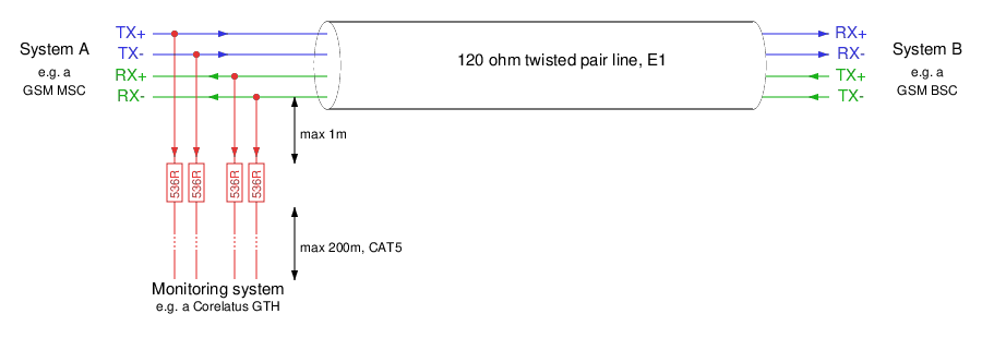
There's an important note on the schematic: "max 1m" cable from the tap-in point to the resistors in the monitor point. The shorter the distance from the tap-in point to the resistors, the better. In many cases, it's possible to mount the resistors just a few millimetres from the tap-in point.
A practical lab monitor point
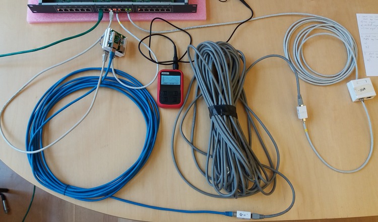
To demonstrate what happens to an E1 signal, we created a live link in our lab, with connections just like in an operator's network. We've used a 1m long cable, the maximum allowed, from the tap-in point to the resistors. We then looked at the signal using a low-cost handheld oscilloscope.
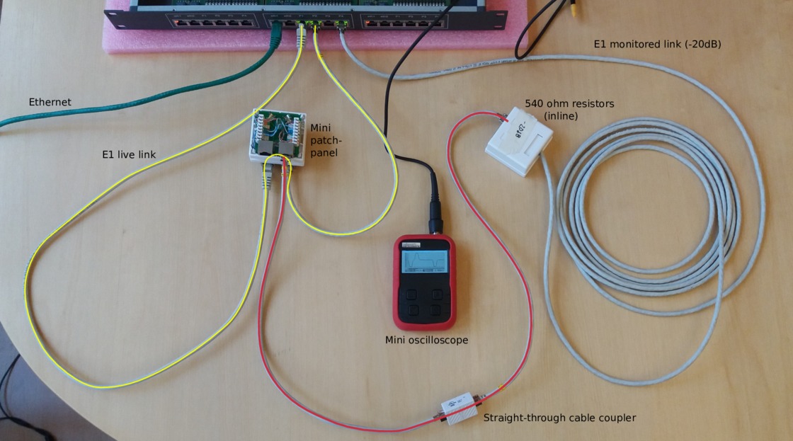
The chassis at the top of the photo is a Corelatus Messenger 2.1 with three modules in it. Messenger is normally used as an active part of an E1 network, e.g. to implement a voicemail system. We're only using the center module, which has two ethernet ports and eight E1/T1 ports. The green cable is the ethernet cable used to control the system.
The yellow line is the live E1 link. It goes from port 'pcm1A' to a break-out box with punch blocks and then on to port 'pcm2A'. We can measure the number of bit errors on the live link. The punch blocks are the same as the ones operators have mounted in racks in their distribution frames.
The red line taps in to the live E1 link at the punch blocks. The length of this red line is critical: if it's too long then signal reflections from the 536 ohm resistors at the end of the red line will disturb the live link. Corelatus specifies a maximum length of 1m for this red line, in the above example we've used two 0.5m cables. In examples further down the page, we'll increase that to see how bad things can get. The red line leads to a box containing the monitoring resistors and then a 5m long cable back to the Messenger 2.1, where we've configured the incoming port to expect an attenuated signal. The length of the cable from the resistors to the monitoring equipment is not critical, it can be up to 200m.
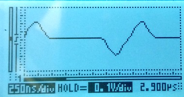
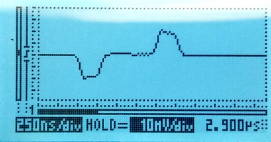
Here's what the signals on this setup look like. On the left, the live signal and on the right the monitored signal, which is attenuated by 20dB. Both signals are clean and have the expected shape.
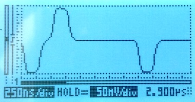
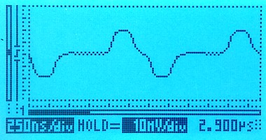
The scope indicates the scale on-screen; the horizontal (time) scale on both is the same, the vertical scales are different. We're measuring through an x10 oscilloscope probe in all cases.
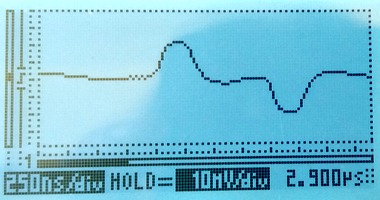
Extending the red line to 10m
A 10m long tap line is out of spec. A real installation should not have such a long tap line. We expect the signal to go from the tap-in point, partially bounce from the resistor box and then interfere with the live signal. The time for a signal to travel down a 10m line, bounce, and travel back up again is approximately 100ns. 100ns is roughly one third of a division on the scope image, so we expect the damage to be that pulses change shape, rather than new pulses appearing between real pulses. The scope images show that the live signal (left) is damaged, whereas the monitored signal (right) is hardly affected:
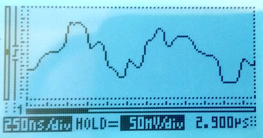
Extending the red line to 35m
Using a 35m long cable to tap in will give a reflection after approximately 350ns. The damage to the live signal is severe, but the monitored signal still looks mostly OK:
The disturbance on the live link is so severe that the live link fails completely. Framing is lost; moving the live link from status "OK" to "LFA" and several other layer 1 error counters (e.g. code violation) increase rapidly. Another simple indication that the link has failed is that the LEDs on the live link have changed colour to orange, they're visible at the top of this photo:
Probing E1 lines with an oscilloscope
The proper way to measure balanced E1 signals in the lab is with a two-channel oscilloscope, with one probe on each of the E1's conductors. The scope can then display the result in differential, i.e. A-B, mode, with no risk of accidentally grounding one side of the E1.
Since the Vellemann oscilloscope only has one channel, there's no A-B mode. So we have no choice but to connect the probe's "ground" to one conductor and the probe's tip to the other. This works fine, and there are no concerns about grounding since the scope is normally battery powered.
The Velleman oscilloscope is cheap and this was the first time we used it, so we checked the measurements using a high quality analog oscilloscope, a Tektronix 2445. The measurements agree well.
We were pleasantly surprised by the Vellemann oscilloscope. It's by far the cheapest Distrelec have, but it works nicely. We left it in the default 'auto' mode and just pressed the 'hold' button a few times for each measurement to get a trace with a couple of pulses in it. It's easily small and cheap enough to take along to a site. (Corelatus has no association with Vellemann or Distrelec, except as a customer. We recommend this scope because it is useful in our experience. We're not paid to recommend it.)
Permalink | Tags: GTH, telecom-signalling